How to Ventilate an Electrical Cabinet: 4 Airflow Configurations
September 26, 2026
Industrial automation panels, motor control centers, and power distribution systems rely heavily on sensitive electronics such as programmable logic controllers (PLCs), variable frequency drives (VFDs), power supplies, and electromechanical relays. During normal operation, these components dissipate electrical energy as heat. If this thermal energy remains trapped inside the enclosure, internal temperatures can exceed manufacturer limits, leading to premature component degradation, nuisance tripping, or complete system failure.
Implementing proper electrical cabinet ventilation is essential for maintaining reliable operation and extending the service life of industrial hardware. However, there is no single airflow configuration that fits every enclosure. Selecting the right approach depends on variables such as internal heat load, cabinet dimensions, ambient temperature, component layout, and environmental contamination levels.
How Airflow Works Inside an Electrical Cabinet
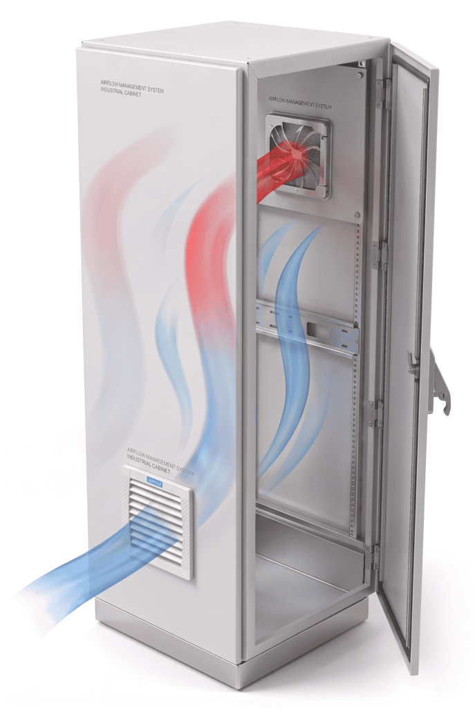
At its core, enclosure thermal management relies on convective heat transfer. Heat generated by internal devices warms the surrounding air. Because warm air is less dense than cool air, it naturally expands and rises toward the top of the enclosure.
The fundamental thermodynamic mechanism follows a simple path:
Cool air enters through a lower intake point (either passively or via a forced fan).
Heat is absorbed as the air flows across internal components.
Warm air rises and exits through an upper exhaust opening or outlet.
This ventilation process transfers thermal energy from the interior of the enclosure directly to the surrounding plant environment.
Crucial Technical Note: Ventilation relies on the ambient air to cool internal components. As a result, standard ventilation cannot cool an electrical cabinet below the ambient temperature of the surrounding room or workspace. If ambient temperatures are excessively high, forced ventilation alone may be insufficient.
4 Ways to Use Fan Filters and Exhaust Ventilation
Depending on the thermal profile and physical constraints of your control panel, engineers can choose from four distinct airflow configurations.
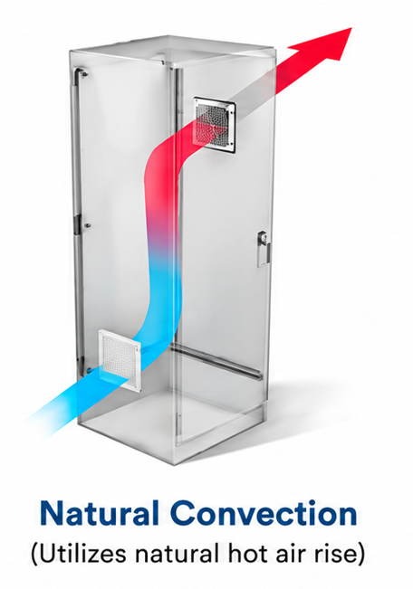
1. Natural Convection
Natural convection is the simplest, passive method for managing low-level heat loads without using powered electrical components.
How it works: Cooler ambient air enters through a lower ventilation opening or louvered filter. As internal components generate heat, the air warms up, becomes buoyant, and rises through the cabinet, eventually exiting through an upper ventilation opening.
Advantages: Operates without electrical power, involves zero mechanical wear parts, and requires minimal maintenance.
Limitations: Provides lower volumetric airflow than forced systems. Its effectiveness depends entirely on the temperature difference between the interior and exterior, the total surface area of the cabinet, and the geometry of the ventilation openings.
Typical Applications: Small enclosures with low heat loads, panels housing minimal heat-dissipating components, and installations where ambient temperatures are consistently mild.
Image 1 Conceptual Description: A semi-transparent industrial electrical enclosure illustrating natural convection. The diagram shows lower air entry, upward-moving airflow arrows, an upper warm-air exit, and the absence of any powered fan.
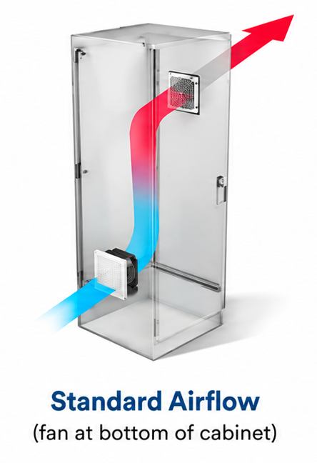
2. Standard Airflow — Fan at the Bottom of the Cabinet
When natural convection cannot overcome internal thermal loads, engineers turn to forced mechanical ventilation. The most common configuration places a fan filter at the lower section of the cabinet.
How it works: A powered fan draws ambient air through a filter pad, removing airborne dust and particulate matter. This cool, filtered air enters the lower portion of the enclosure, moves upward across internal components, and expels warm air through an upper outlet or passive exhaust filter.
Airflow Path: Bottom intake (fan filter) → upward through the components → top exhaust (passive exhaust filter). This forced flow moves the same way as naturally rising warm air, so the fan and natural convection push in the same direction.
Role of LEIPOLE FKL55 Series: The LEIPOLE FKL55 Series serves as an ideal bottom-mounted fan filter for forced filtered air intake, introducing clean, regulated airflow into the enclosure base to establish a stable upward current.
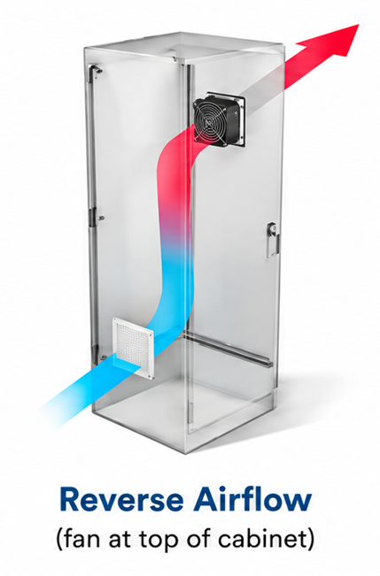
3. Reverse Airflow — Fan at the Top of the Cabinet
In specific panel layouts, the fan filter can be positioned near the upper section of the cabinet with the airflow direction reversed.
How it works: Instead of forcing air in from the bottom, the fan is mounted toward the top of the enclosure, operating in a reverse orientation based on the selected fan motor configuration and cabinet layout.
Practical Reasons for Consideration: Engineers may select this setup to accommodate rigid installation constraints, complex internal component layouts, specific contamination control requirements, or unique thermal management goals.
Engineering Perspective: Reverse airflow is an alternative design strategy rather than an inherently incorrect method. While warm air naturally rises, the correct airflow path is determined by the overall thermal design of the cabinet and how cooling air must interact with dense component clusters.
Role of LEIPOLE FKL55 Series: The versatile configuration of the FKL55 fan-filter unit allows it to be adapted to different mounting positions and airflow orientations depending on specific engineering requirements.
Image 3 Conceptual Description: A semi-transparent industrial enclosure showing the LEIPOLE FKL55 fan filter positioned at the upper section of the cabinet, with clear arrows indicating a reversed airflow direction through the system.
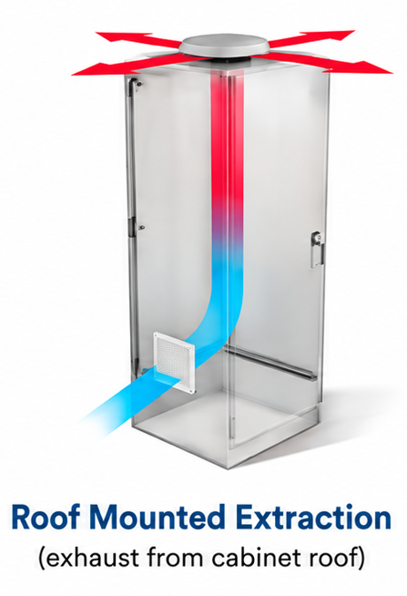
4. Roof Mounted Extraction
Instead of pushing air into the enclosure from the side or bottom, roof-mounted extraction uses an active exhaust fan located on the top of the electrical cabinet.
How it works: The top-mounted exhaust fan actively pulls warm air out from the highest point of the enclosure, creating a negative pressure differential that draws fresh ambient air inward through lower intake filters
Role of LEIPOLE DVP Series: The LEIPOLE DVP Series is designed specifically as a roof-mounted extraction and top exhaust solution for industrial cabinets. Because heat naturally accumulates at the ceiling of an enclosure, top extraction establishes an efficient, direct airflow path that pairs effectively with lower intake filters.
Image 4 Conceptual Description: A semi-transparent industrial enclosure showing the LEIPOLE DVP series mounted on the roof. Clear upward arrows demonstrate warm air being extracted from the top, while replacement air enters through a lower opening.
Standard Airflow vs. Reverse Airflow vs. Roof Mounted Extraction
Configuration
Fan Position
Main Airflow Function
Typical Airflow Direction
Main Consideration
Natural Convection
None (Passive)
Thermal buoyancy transfer
Upward (Passive)
Limited heat load capacity
Standard Airflow
Bottom of cabinet
Filtered forced intake
Upward from base
Matches natural warm air rise
Reverse Airflow
Top of cabinet
Configured installation path
Varies by design
Component layout and constraints
Roof Mounted Extraction
Top / Roof of cabinet
Active hot-air extraction
Upward and out through roof
Capitalizes on upper heat accumulation
How to Choose the Right Electrical Cabinet Airflow Configuration
Determining the proper method for control cabinet ventilation requires a systematic evaluation of physical and environmental parameters:
Check internal heat load: Calculate the total wattage dissipated by all internal devices.
Check ambient temperature: Measure the maximum expected temperature outside the enclosure.
Check cabinet dimensions: Determine the available surface area and internal volume.
Check component placement: Identify high-heat components (such as VFDs or transformers) that require direct airflow.
Check dust and environmental conditions: Evaluate particulate levels in the facility to determine required filter density.
Determine intake vs. exhaust needs: Decide whether forced bottom intake or active roof extraction best suits the cabinet geometry.
Define intended airflow direction: Select between standard, reverse, or natural flow paths.
Check ventilation sufficiency: Verify that the chosen airflow volume can maintain internal temperatures within acceptable limits.
Enclosure designers must always account for filter resistance, pressure losses, and cabinet geometry to ensure the selected fan delivers adequate airflow against system backpressure.
FKL55 Fan Filter and DVP Roof-Mounted Extraction
While both product lines contribute to electrical enclosure cooling, they serve distinct operational roles:
LEIPOLE FKL55 Series: Primarily engineered for filtered forced-air intake. When mounted toward the lower section of an enclosure, it introduces clean, pressurized ambient air to sweep upward across internal electronics.
LEIPOLE DVP Series: Primarily engineered for roof-mounted hot-air extraction. By pulling thermal buildup directly from the top of the cabinet, it prevents heat from pooling near sensitive top-mounted components.
Depending on thermal calculations and enclosure geometry, combining an intake fan filter with a roof-mounted extraction unit can form an effective, balanced forced-ventilation setup. However, such configurations must be engineered based on specific airflow and pressure requirements rather than applied as a universal standard.
When Is Ventilation Not Enough?
There are operating environments where standard electrical enclosure ventilation is simply insufficient. Closed-loop or alternative cooling methods should be considered when:
Internal heat loads are exceptionally high.
Plant ambient temperatures routinely exceed maximum component ratings.
Internal cabinet temperatures must be maintained below ambient temperature.
Enclosures must remain completely sealed (e.g., washdown NEMA 4X or IP69K environments) to block moisture or corrosive chemicals.
In these demanding scenarios, industrial air conditioners or closed-loop air-to-air heat exchangers are required, as they isolate internal air from the external environment.
Conclusion
Managing thermal loads effectively relies on understanding the available pathways for heat dissipation. Whether utilizing passive natural convection, standard bottom-up forced airflow, reverse configuration layouts, or top-mounted roof extraction, the correct method depends directly on the cabinet’s heat load, ambient conditions, component layout, and required airflow path.
For technical assistance in selecting the appropriate fan filter or roof-mounted extraction solution for your control panel, prepare your enclosure dimensions, internal heat load, ambient temperature, and required airflow parameters, and consult with the LEIPOLE engineering team.
We use essential cookies to run this site. Optional cookies help us understand visits and campaign sources, without cross-site advertising cookies.
Choose cookies & learn more
Essential cookies support forms, security and saved settings. They stay enabled.
Your choice is saved in this browser until you change it or clear site data. Change it anytime using “Cookie settings” in the footer. Chat and video services load when you open them.