Basic knowledge
What is a terminal grounding busbar?
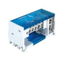
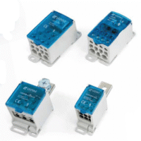
An electric ground bar with an insulating support that can be directly installed on the enclosure and the grounding wire is fixed by screws to ensure safety and convenience.
Safety: By providing a low-impedance path, it’s important to prevent hazards such as electric shock and fire by safely directed the fault current to the ground .
Electromagnetic compatibility: Reduce Electro-Magnetic Interference (EMI) to ensure the normal operation of the equipment.
Common misunderstandings
Ignoring material selection: people usually think that any conductive material is suitable for the grounding busbar. In fact, copper or brass and aluminum are widely used due to their excellent conductivity and corrosion resistance.
Improper size: Mistakenly thinking that all terminal grounding busbar are universal in size. In fact, the size of neutral bus bar should be selected according to the current load and application environment of the system.
Installation precautions:
Connection tightening: Make sure all connection points are firmly fixed by screws to prevent looseness and poor contact.
Anti-corrosion measures: In some harsh environment such as humidity or corrosion, consider using tin-plated or nickel-plated busbars.
Maintenance suggestions: Regularly check the connection condition of the grounding busbar to ensure that there is no looseness, corrosion or overheating.
1. The Real Role of a Ground Bus Bar
A ground bus bar acts as a single, low‑impedance reference point for all protective earth connections. In busbar earthing systems, this keeps equipment chassis and exposed conductive parts at the same potential, preventing dangerous voltage differences during faults.
Neutral ground bus bar: Used in service panels to bond the neutral conductor to the grounding electrode conductor—only at the service entrance to avoid parallel current paths.
Telecom grounding busbar: Installed near telecom racks to provide a direct, low‑resistance path to the facility ground. This minimizes signal noise and protects sensitive telecom gear.
2. Material Matters – Why Copper Rules
Ground bar copper offers the lowest resistance and highest thermal capacity. In high‑fault scenarios, it can safely carry thousands of amps for short durations without damage.
Tinned copper: In harsh environments (marine, outdoor telecom), tin plating prevents oxidation that would otherwise increase contact resistance.
Aluminum is cheaper but more prone to corrosion and galvanic reaction, especially with copper lugs.
3. Size, Thickness, and Hole Layout Secrets
For industrial switchboards, a busbar thickness of 6–10 mm ensures minimal voltage rise during fault current events.
Hole spacing must match the lug type—too close and lugs won’t fit; too far apart wastes panel space.
For telecommunications grounding busbar, ETSI and ANSI/TIA standards specify hole patterns and spacing to ensure compatibility with telecom ground kits.
4. Installation Mistakes to Avoid
Direct contact with painted surfaces: Always scrape paint under mounting points to ensure a direct metallic bond to the enclosure or mount with conductive hardware.
Mixed metal hardware: Avoid mixing stainless steel bolts with bare copper bars without a proper anti‑galvanic barrier.
Loose terminations: Under‑torqued connections create high resistance, heating, and potential arcing.
5. When Replacements Are Necessary
Square D bus bar replacement kits are available when corrosion, mechanical damage, or improper drilling compromises the original bar.
Never reuse a damaged or overheated busbar—heat stress changes copper’s grain structure, reducing its conductivity and mechanical integrity.
6. Application‑Specific Configurations
Neutral ground bus bar: For service entrance bonding only—never inside sub‑panels.
Telecom grounding busbar: Typically wall‑mounted at the top of a telecom rack, with insulated standoffs to avoid unintended bonding points.
Outdoor enclosures: Use IP‑rated ground bars with weatherproof lug covers to prevent water‑induced corrosion.