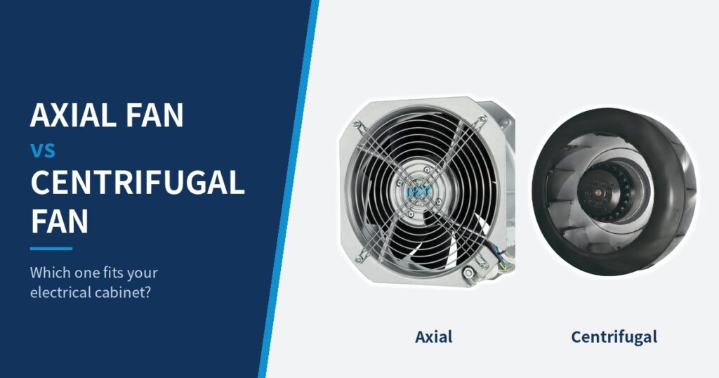
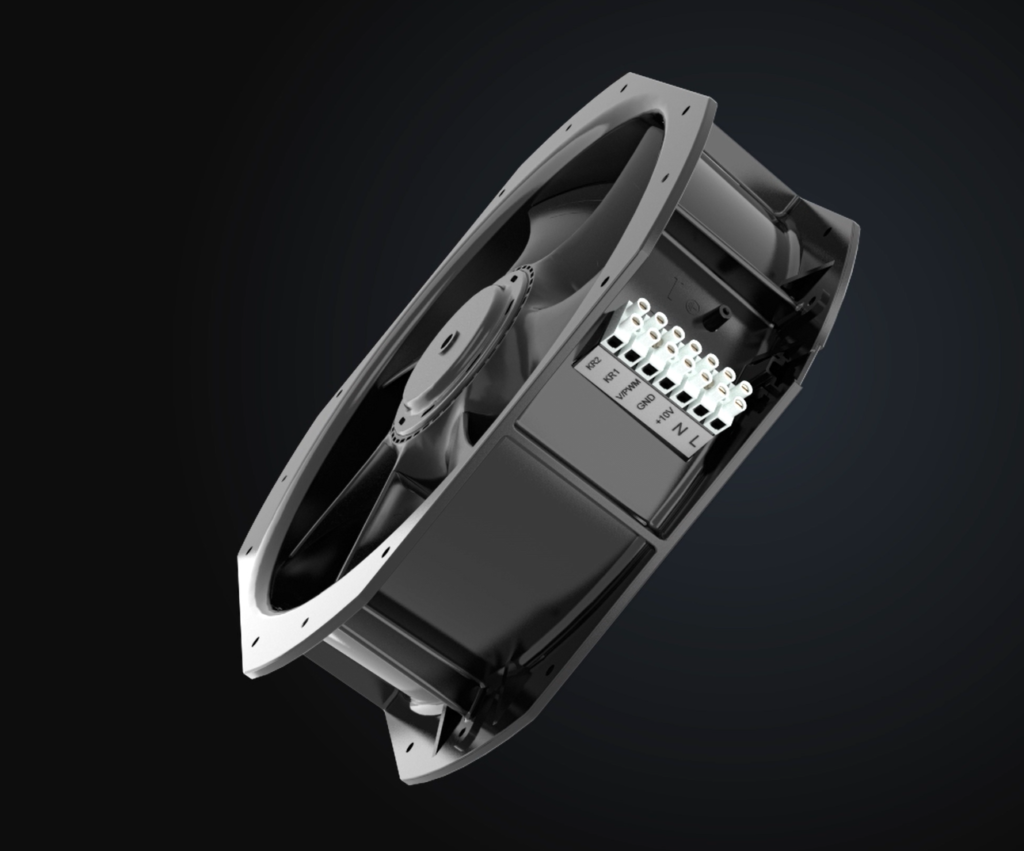
Industrial control panels, automation racks, and power electronics generate significant thermal energy that must be managed to ensure long-term component reliability. When designing advanced thermal management systems for industrial enclosures, engineers increasingly rely on the pwm fan. Unlike legacy fixed-speed cooling solutions, a pwm fan provides dynamic, precise airflow regulation that adapts to real-time operating conditions.
This technical guide explores how does a PWM fan work, the mechanics of PWM fan speed control, proper PWM fan wiring, and why deploying a 4 wire PWM fan optimizes electrical enclosure cooling fan performance in demanding industrial environments.
What Is a PWM Fan?
A pwm fan is an electromechanical air-moving device equipped with an internal electronic commutation circuit and a dedicated control input that accepts a Pulse Width Modulation signal.
- Technical Clarification: A PWM cooling fan and a standard DC fan are not mutually exclusive concepts. In most industrial applications, a PWM controlled fan is fundamentally a DC-powered fan that features an internal controller and an additional logic-level control line alongside its standard power supply and ground wires.
How Does a PWM Fan Work?
To understand how does a PWM fan work, engineers must look past the main power supply and examine the division of signals within the motor hub. A robust PWM fan speed control architecture relies on three distinct electrical domains operating simultaneously:
- Fan Power Supply: Delivers continuous operating voltage and current to drive the motor windings.
- PWM Control Signal: A square-wave digital pulse sent from an external controller to the fan’s internal microcontroller.
- Tachometer / Speed Feedback: A dedicated pulse output sent from the fan back to the controller to monitor operational speed.
Understanding Duty Cycle
The PWM signal does not alter or chop the main operating voltage. Instead, it pulses a low-voltage control line at a fixed frequency. The key parameter is the duty cycle—the ratio of the pulse ON time to the total period, expressed as a percentage.
Critical Engineering Note: Do not assume that a specific duty cycle (e.g., 50%) maps linearly to a specific RPM across all models. The exact relationship between duty cycle and actual fan speed is governed by the fan’s internal firmware and manufacturer specifications.
What Is a 4-Wire PWM Fan?
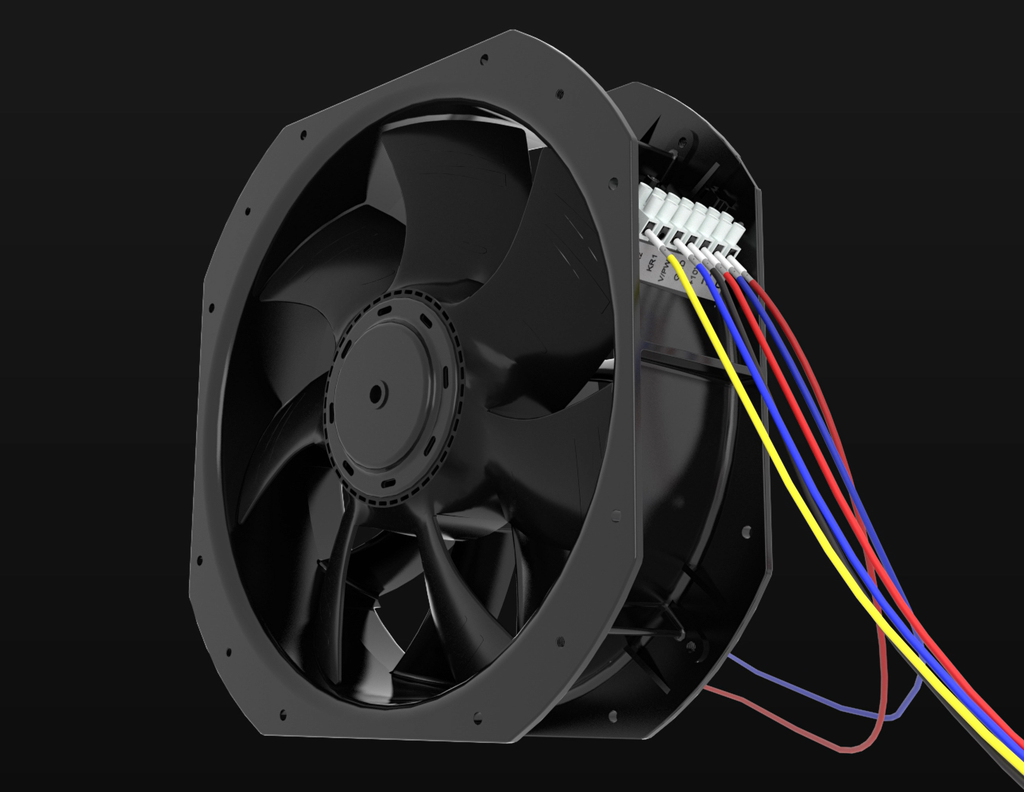
The industry standard for advanced thermal management is the 4 wire PWM fan. Unlike older 2-wire or 3-wire designs, the 4-wire architecture completely decouples power delivery from speed control and monitoring.
The common functional arrangement of a 4 wire PWM fan includes:
- Power: Supplies continuous DC voltage to the motor.
- Ground: Completes the electrical circuit for power and logic signals.
- PWM Control: Receives the external square-wave speed command signal.
- Tachometer / Speed Feedback: Outputs square-wave pulses proportional to the fan’s rotational speed for real-time monitoring.
Important: Never assume that all manufacturers use identical wire colors or pin assignments. Always verify the exact pinout, signal voltage levels, and frequency requirements in the manufacturer’s official technical datasheet.
PWM Fan Wiring: How Does It Work?
Proper PWM fan wiring ensures reliable communication between the system controller and the cooling device. In a typical integration layout, the connections are mapped as follows:
- System Power Supply → Fan power input
- Enclosure Controller / PLC Output → Fan PWM control input
- Fan Tachometer Output → Controller feedback input (for closed-loop monitoring)
Common Wiring Pitfall
Never treat the PWM control signal wire as the primary power supply. Injecting high-current power directly into the low-voltage control line will permanently damage the internal logic circuitry.
PWM Fan vs Voltage-Controlled Fan
Comparing PWM speed control to supply-voltage speed control highlights distinct operational trade-offs for industrial designers:
| Feature | PWM Speed Control | Supply-Voltage Speed Control |
| Control Flexibility | Wide-range speed modulation without starving motor voltage. | Limited low-end range; risk of motor stalling at reduced voltages. |
| System Integration | Requires a dedicated control channel and 4-wire interface. | Works with basic variable DC power supplies. |
| Speed Monitoring | Natively supported via tachometer feedback line. | Often lacks speed verification or requires external sensors. |
| Thermal Efficiency | Maintains full motor torque efficiency across speeds. | Can cause motor heating issues at reduced voltages. |
Why Use PWM Fans for Electrical Enclosure Cooling?
When selecting an electrical enclosure cooling fan or cabinet cooling fan, maintaining optimal internal temperatures is critical for PLC longevity, inverter reliability, and relay performance. PWM axial fan solutions excel in these environments by matching airflow dynamically to thermal loads.
How the Control Sequence Operates
- Temperature Sensor: Detects rising internal cabinet heat within the enclosure.
- Controller / PLC: Processes the thermal data against programmed setpoints.
- PWM Signal: Adjusts the duty cycle transmitted to the PWM cooling fan.
- Fan Speed & Airflow: Modulates rotational speed, modifying volumetric airflow.
- Cabinet Temperature: Stabilizes in response to matched cooling demand.
What to Consider When Selecting a PWM Fan
When choosing an industrial cooling fan for a control panel, evaluate the following parameters:
- Supply Voltage: Ensure compatibility with panel power rails.
- Airflow and Static Pressure: Never rely solely on free-air CFM or m³/h. Evaluate performance against actual system resistance imposed by fan filters, inlet grilles, internal cabling, and heat exchangers.
- PWM Control Compatibility: Verify frequency ranges and logic-level thresholds.
- Speed Feedback: Confirm whether tachometer monitoring is required by your PLC.
- Environmental Ratings: Check IP ratings for dust and humidity resistance.
- Installation Requirements: Verify physical dimensions and mounting orientation.
Common PWM Fan Wiring and Control Mistakes
- Treating PWM as Power: Feeding main power through the PWM control line.
- Assuming Universal Pinouts: Neglecting to check manufacturer datasheets for unique wire color codes.
- Assuming Linear Scaling: Expecting a rigid, universal relationship between duty cycle and RPM.
- Ignoring Static Pressure: Failing to account for pressure drops across dirty filter media.
PWM Fan Application Examples
- Industrial Control Panels: Variable-speed cooling for densely packed PLC racks to minimize noise and dust ingestion during low-load periods.
- Power Electronics Enclosures: Thermal regulation for variable frequency drives (VFDs) and soft starters where heat load fluctuates with motor torque.
- CNC and Machine Tools: Protecting sensitive CNC controllers from workshop ambient spikes.
Frequently Asked Questions
What is a PWM fan?
Direct Answer: A PWM fan is an electromechanical cooling fan featuring an integrated control circuit that accepts a Pulse Width Modulation signal to adjust its operational speed.
Explanation: Unlike traditional fans that rely on fluctuating main voltage, a PWM fan maintains steady power while a separate digital pulse signal commands the motor speed.
How does a PWM fan control speed?
Direct Answer: A PWM fan controls speed by interpreting the duty cycle of an external square-wave control signal.
Explanation: The controller varies the percentage of ON time versus OFF time in the control pulse, which the fan’s internal electronics use to regulate motor commutation speed.
What is a 4-wire PWM fan?
Direct Answer: A 4-wire PWM fan is a fan design that separates power delivery, grounding, speed control, and speed monitoring into four distinct lines.
Explanation: The four connections typically consist of power, ground, PWM control input, and tachometer feedback.
What are the four wires on a PWM fan?
Direct Answer: The four wires are power, ground, PWM control signal, and tachometer feedback.
Explanation: This configuration allows continuous motor power while enabling precise external speed commands and real-time RPM monitoring.
Does a PWM fan use PWM as its power supply?
Direct Answer: No, a PWM fan does not use the PWM signal as its main power supply.
Explanation: The fan requires a separate, continuous DC power source to drive the motor, while the PWM signal acts purely as a low-power digital command input.
Can PWM fans be used for electrical cabinet cooling?
Direct Answer: Yes, PWM fans are widely and effectively used for electrical cabinet cooling.
Explanation: They allow control panels to dynamically modulate airflow based on internal temperature sensors, optimizing energy use and reducing noise.
Does PWM reduce fan noise?
Direct Answer: Yes, PWM speed control can significantly reduce operational noise.
Explanation: By slowing the fan down during periods of low thermal demand, acoustic emissions drop compared to constant high-speed running.
Does PWM fan speed increase linearly with duty cycle?
Direct Answer: Not necessarily; fan speed does not always scale in a strict linear fashion with duty cycle.
Explanation: The exact response curve depends entirely on the specific fan’s internal firmware and manufacturer engineering design.
What is the difference between a PWM fan and a DC fan?
Direct Answer: A PWM fan and a DC fan are not mutually exclusive; a PWM fan is typically a DC fan equipped with a dedicated control input.
Explanation: While standard DC fans run at a fixed speed based on input voltage, PWM DC fans include extra circuitry to interpret external speed signals.
Conclusion
Implementing a pwm fan within industrial automation panels and electrical enclosures offers a sophisticated approach to thermal management. By decoupling power supply from speed control, engineers achieve precise airflow regulation, reduced acoustic noise, and extended equipment lifespan.
Optimize Your Thermal Management with LEIPOLE
Selecting the right cooling components requires careful evaluation of electrical and environmental constraints. Contact LEIPOLE today for expert assistance with:
- Airflow selection and volumetric calculations
- Static-pressure evaluation across filters and heat exchangers
- Voltage selection and PWM control compatibility
- Comprehensive electrical enclosure cooling fan recommendations tailored to your application