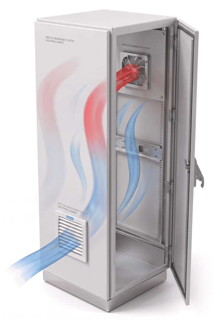
Why Is Proper Airflow Evaluation So Critical?
In industrial fan environments—think electrical cabinets, energy storage systems, and EV charging stations—your fan’s airflow rating is the single biggest factor in reliable heat removal and cost control:
- Too Much Airflow?
- Energy bills skyrocket.
- Excessive noise disrupts equipment and personnel.
- Turbulence can create hot spots instead of cooling evenly.
- Too Little Airflow?
- Heat builds up, causing components to overheat.
- Equipment life shortens and warranties void.
- System instability poses safety risks.
Different applications demand very different airflow targets. For example:
- Electrical enclosures: calculate from the heat that ventilation must remove and the allowed internal-to-ambient temperature rise; avoid a universal airflow-per-kW value.
- Energy-storage PCS enclosures: use the equipment heat losses, permitted temperatures and system pressure drop.
- Outdoor charging kiosks: account for solar heat, filters and weather protection using project conditions and fan curves.
How Do You Estimate Required Airflow from Your Heat Load?

What Is “Heat Load” and How Do You Calculate It?
Heat load (Q), measured in watts (W), is the total continuous heat your system generates—transformer losses, rectifier heat, control-board power draw, and so on.
Basic formula:
Q=∑PlossQ = \sum P_{\text{loss}}
Which Variables Drive Your Airflow Calculation?
- Temperature Rise (∆T): Your allowable internal‑to‑ambient temperature difference (typically 10–15 °C).
- Specific Heat of Air (cₚ): Approximately 1.005 kJ/kg·K.
- Air Density (ρ): Roughly 1.2 kg/m³.
Airflow formula: V̇ = 3600 × Q_air / (ρ × c_p × ΔT). Use V̇ in m³/h, Q_air in W, ρ in kg/m³, c_p in J/(kg·K), and ΔT in K. Q_air is the heat to be removed by ventilation after enclosure surface heat transfer is considered.
Is There a Quick “Rule‑of‑Thumb”?
- With ρ = 1.2 kg/m³ and c_p = 1005 J/(kg·K), V̇ ≈ 2.985 × Q_air / ΔT. For 1000 W removed entirely by air at a 10–15 K rise, this gives approximately 199–299 m³/h. The current tool uses an engineering factor of 3.1, giving approximately 207–310 m³/h under the same assumption.
- Precision method: Use the physics‑based formula above and adjust ∆T for your specific environment.
What Real‑World Factors Affect Your Fan’s Delivered Airflow?
Does Installation Geometry Matter?
- Inlet/Outlet Openings: Smaller filters, grilles, or louvers increase resistance and cut airflow.
- Ductwork & elbows: calculate their pressure loss and compare it with the fan curve; the airflow reduction is specific to the system.
How Do Filters and Seals Play a Role?
- Filter Resistance: A new filter has low resistance, but as it loads with dust, resistance—and energy consumption—climbs.
- Seal Integrity: Gaps around the fan create bypass airflow, reducing the cooling directed where you need it.
- Component Placement: Cables or boards placed too close to the fan inlet can create bottlenecks.
Which Online Tools Make Fan Airflow Calculations a Breeze?

Meet the LEIPOLE Airflow Sizing & Fan Selection Tool
- Instant Calculations: Enter your heat load, ∆T target, and environment data—get results in seconds.
- Save and share: save inputs in the browser, copy a link, or use Print/PDF to print the calculation or save a PDF through the browser.
- Selection limits: the tool does not assess IP ratings or calculate filter and duct pressure losses. Confirm those requirements separately.
- Ready to Try?
Access it here:
https://leipole.com.sg/leipole-electrical-cabinet-cooling-fan-selection-tool/
Templates for Your Specific Application
- Small, medium and large electrical-cabinet heat-load examples.
- Enter the actual PCS heat losses and operating temperatures for a PCS calculation.
- Enter the actual heat load and ambient conditions for an outdoor EV application.
The current examples populate cabinet heat loads. They do not prescribe mounting details, filter requirements or application-specific certification.
Should You Choose Axial Fan or Centrifugal Fans?
Axial Fan
- High Airflow, Low Static Pressure: Ideal for open‑frame installations.
- Compact Design & Lower Cost.
Centrifugal Fan
- Higher Static Pressure, Moderate Airflow: Best for filtered or ducted systems.
- Handles longer duct runs with ease.
Example Models:
| Application | Selection basis |
|---|---|
| Cabinet cooling | Heat to remove, temperature rise, supply and installed system resistance |
| Energy storage | Equipment losses, environmental conditions and project protection requirements |
| EV charging | Ambient and solar heat, weather protection, filter pressure loss and duty cycle |
What Are the Top Airflow Sizing Pitfalls to Avoid?
- “Bigger Is Better” Myth: Beyond a point, extra airflow doesn’t improve heat removal but blows up your power bill.
- Ignoring System Resistance: Always account for filters, ducts, and elbows in your sizing calculation.
- Overlooking Maintenance: A fan that’s hard to access or service will degrade performance over time.
Who Can Help If You’re Still Unsure?
Free Sizing Guidance from LEIPOLE Experts
- Online Consultations: Get one‑on‑one advice to dial in your ∆T and airflow targets.
- Remote or On‑Site Heat‑Load Assessments: Detailed analysis and custom recommendations.
- Tailored Solutions: From wind farms to EV chargers, LEIPOLE integrates fans, heaters, controllers, and transformers for turn‑key cooling.
Use the LEIPOLE fan selection tool for an initial heat-balance estimate, then confirm the installed operating point and model with the technical team.