The efficiency of a variable frequency drive (VFD) is typically around 97–98%, which means that approximately 2–3% of the electrical energy is converted into heat. This heat generation is significantly higher than that of common electrical components such as switches and AC contactors.
Standard distribution enclosures are generally designed for conventional components like switches and AC contactors. When this type of enclosure is used for VFD applications, careful planning of the internal component layout is required to ensure proper airflow and effective heat dissipation.
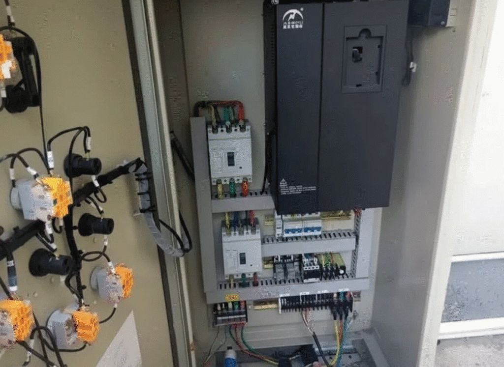
The failure rate of a variable frequency drive (VFD) increases exponentially as temperature rises, while its service life decreases exponentially with increasing temperature. For every 10 °C increase in ambient temperature, the average service life of a VFD is reduced by half.
During operation, a VFD carries high current, resulting in significant heat generation. The impact of this heat must not be overlooked. To estimate the amount of heat generated by a VFD, the following formula can be used:
Approximate heat dissipation = VFD rated power (kW) × 55 [W]
If the VFD is rated for constant-torque loads (overload capacity 150% × 60 s), is equipped with a DC reactor or AC reactor, and is installed inside an enclosure, the heat dissipation will be higher. In such cases, it is recommended to install the reactor on the side or above the VFD. The heat generated by the VFD can then be estimated using the following formula:
Approximate heat dissipation = VFD rated power (kW) × 60 [W]
If a braking resistor is installed inside the enclosure, special attention is required because braking resistors generate a large amount of heat. The braking resistor should be installed separately from the VFD, for example at the top of the enclosure or in a side compartment.
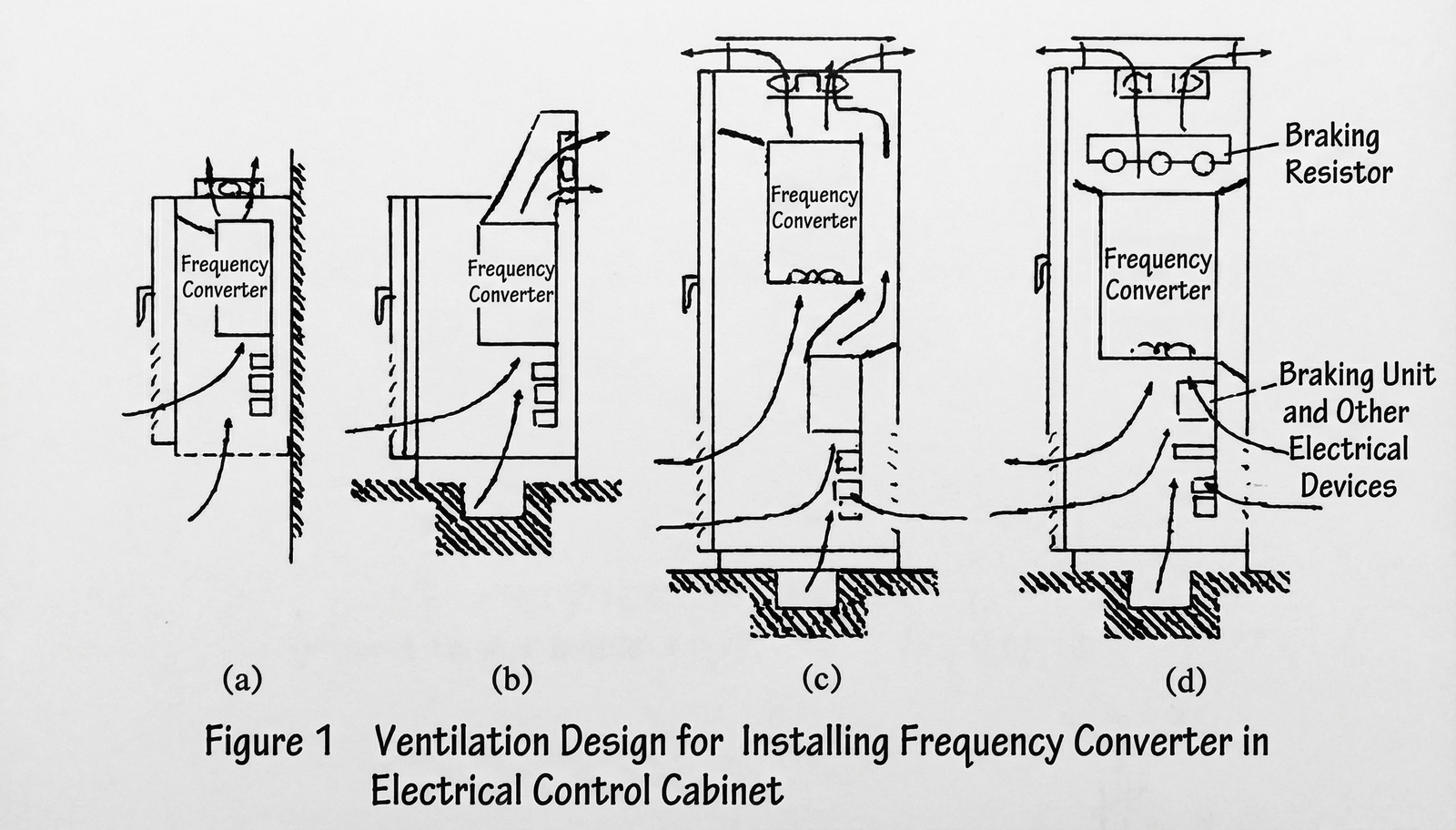
Figure 1 illustrates several typical airflow configurations for installing VFDs inside electrical control cabinets.
In Figure 1(a), a wall-mounted control cabinet is equipped with an exhaust fan at the top to extract hot air.
In Figure 1(b), a console-type control cabinet uses an exhaust fan installed at the upper section to remove hot air.
In Figure 1(c), a large floor-standing control cabinet is fitted with a high-capacity exhaust fan at the top, while the cable trench and the lower part of the cabinet must provide adequate air inlets.
In Figure 1(d), a large floor-standing control cabinet contains both a control unit and a braking resistor; a high-capacity exhaust fan is installed at the top, and sufficient air inlets are required in the cable trench and the lower section of the cabinet.
When arranging VFDs inside an electrical control cabinet, the design principles for the cabinet airflow are as follows:
- The electrical control cabinet must have a forced ventilation circuit, with smooth airflow that follows the principle of gradual directional changes. The fans installed on the cabinet should provide 30–50% more total airflow than the VFD’s own fans.
- The cabinet’s airflow path should generally include low-resistance air inlets. In environments with dust or contaminants, the inlets should be equipped with filters. The filter resistance should be minimal, and filters must be regularly cleaned to prevent clogging.
- Air inside the cabinet should not flow directly from inlet to outlet (short-circuiting), nor should hot air recirculate. Guides and baffles should be installed inside the cabinet. Baffles serve to block direct airflow and prevent hot air recirculation, improving the internal airflow pattern and enhancing cooling efficiency.
- In cabinets without a specially designed forced-ventilation duct, a single VFD should be installed with adequate clearance from surrounding components and the cabinet walls, especially above and below to ensure smooth airflow. Depending on the VFD’s power rating, there should be at least 120–300 mm of vertical space, and at least 50 mm of clearance on the sides and front.
- When the ambient temperature around the VFD exceeds 40 °C, VFDs equipped with ventilation covers should have the covers removed to allow air to flow freely into the drive.
Keep your VFDs cool and reliable with LEIPOLE axial fans—high airflow, low noise, and built to last. Explore our solutions here
d40p1gs full load amps 575v